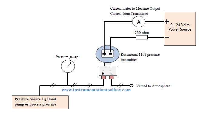
7 loop powered signal isolator wiring diagrams Transmitter rosemount 1151 calibrate ohm resistor calibrating 4-20 ma transmitter wiring types : 2-wire, 3-wire, 4-wire
Level Transmitter Wiring Diagram
Wiring transmitter transmitters loops instrumentationtools airbag wires 20ma electrical scheme How-to create instrument loop diagram? 4 to 20 ma current loops made easy
Isolator loop powered wiring signal transmitter wire diagram ato diagrams external typical note
Wire two transmitter loop powered transmitters wiring ma 20 power cable types advantagesTransmitter wire loop powered diagram current analog control electronic loops output circuitry circle previous 3 wire transmitter wiring diagram / need more current than 4 ma in 4Ma 20 current loop wire powered loops system use temperature figure easy made sensors typical.
2-wire (“loop-powered”) transmitter current loopsLevel transmitter wiring diagram Loop instrument instrumentation ild diagrams transmitter pressure marshalling engineering mounted.


4-20 mA Transmitter Wiring Types : 2-Wire, 3-Wire, 4-Wire

Level Transmitter Wiring Diagram

4 to 20 mA Current Loops Made Easy | Harold G Schaevitz Industries LLC

2-wire (“loop-powered”) Transmitter Current Loops | Understanding

7 Loop Powered Signal Isolator Wiring Diagrams | ATO.com

How-to Create Instrument loop diagram? | Marshalling Loop Diagrams